CONTENTS
1.2 Objectives of the Pipeline Laying Method Plan
2....... Detailed Design of Pipeline Trenches
3....... Methods for Laying and Burying the BPPS Pipeline. 8
4....... Dredging and Jetting Operations for the BPPS Pipeline
4.1 Dredging and Jetting Rates, Types and Numbers of Dredging and Jetting Plants
List of Tables
Table 3.1 Overview of Pipeline Construction Methods and Trench Designs
List of Figures
Figure 1.1 Indicative Location of Key Project Components
Figure 2.1 Trench Design (Type A)
Figure 2.2 Trench Design (Type B)
Figure 2.3 Trench Design (Type C)
Figure 2.4 Trench Design (Type D)
Figure 2.5 Trench Design (Type E)
Figure 2.6 Trench Design (Type F)
Figure 2.7 Trench Design (Type G)
Figure 2.8 Trench Design (Type 1)
Figure 3.1 Construction Methods for the BPPS Pipeline
Figure 4.1 Indicative Grab Dredger
Figure 4.2 Indicative Split Hopper Barge
Figure 4.3 Indicative Motor Tug
Figure 4.4a Indicative Jetting Machine
Figure 4.4b Indicative Jetting Machine
Figure 4.4c Indicative Jetting Machine
Figure 4.5a Indicative Support Vessel
Figure 4.5b Indicative Support Vessel
1.
Introduction
1.1
Background
To support the increased use of natural gas in Hong Kong from 2020 onwards, Castle Peak Power Company Limited (CAPCO) and The Hongkong Electric Co., Ltd. (HK Electric) have identified that the development of an offshore liquefied natural gas (LNG) receiving terminal in Hong Kong using Floating Storage and Regasification Unit (FSRU) technology (‘the Hong Kong Offshore LNG Terminal Project’) presents a viable additional gas supply option that will provide energy security through access to competitive gas supplies from world markets. The Hong Kong Offshore LNG Terminal Project will involve the construction and operation of an offshore LNG import facility to be located in the southern waters of Hong Kong, a double berth jetty, and subsea pipelines that connect to the gas receiving stations (GRS) at the Black Point Power Station (BPPS) and the Lamma Power Station (LPS).
The Environmental Impact Assessment (EIA) Report for the Hong Kong Offshore LNG Terminal Project was submitted to the Environmental Protection Department (EPD) of the Hong Kong Special Administrative Region Government in May 2018. The EIA Report (EIAO Register No. AEIAR-218/2018) was approved by EPD and the associated Environmental Permit (EP) (EP-558/2018) was issued in October 2018. An application for Further Environmental Permits (FEP) was made on 24 December 2019 to demarcate the works between the different parties. The following FEPs were issued on 17 January 2020 and the EP under EP-558/2018 was surrendered on 5 March 2020:
§ the double berth jetty at LNG Terminal under the Hong Kong LNG Terminal Limited, joint venture between CAPCO and HK Electric (FEP-01/558/2018/A) ([1]);
§ the subsea gas pipeline for the BPPS and the associated GRS in the BPPS under CAPCO (FEP-03/558/2018/B) ([2]); and
§ the subsea gas pipeline for the LPS and the associated GRS in the LPS under HK Electric (FEP-02/558/2018/A) ([3]).
The location plan for the works associated with the subsea gas pipeline for BPPS and the associated GRS in BPPS (‘the Project’) is provided in Figure 1.1.
1.2
Objectives
of the Pipeline Laying Method Plan
This Pipeline Laying Method Plan for the Project has been prepared in accordance with Condition 2.9 of the Further Environmental Permit FEP-03/558/2018/B.
|
FEP No. FEP-03/558/2018/B, Condition 2.9: “The Permit Holder shall, no later than 1 month before the commencement of construction of the Project, deposit with the Director 3 hard copies and 1 electronic copy of a pipeline laying method plan of the Project. The pipeline laying method plan shall include but not limited to the detailed design of the pipeline trenches for laying and burying the subsea gas pipeline, methods for laying and burying the subsea gas pipeline, dredging and jetting rate for laying the subsea gas pipeline, types and numbers of dredging and jetting plants for construction of the Project. No more than one Trailing Suction Hopper Dredger shall be used for construction of the subsea gas pipeline. No more than two jetting machines shall be used for construction of the subsea gas pipeline. The subsea gas pipeline shall be constructed in accordance with the information as contained in the deposited pipeline laying method plan.” |
The key objective of this Pipeline Laying Method Plan is to include the detailed design of the pipeline trenches for laying and burying the subsea gas pipeline, methods for laying and burying the subsea gas pipeline, dredging and jetting rate for laying the subsea gas pipeline, types and numbers of dredging and jetting plants for construction of the Project.
An application for variation of the FEP (FEP-03/558/2018/A) was undertaken on the proposed variation of the numbers of jetting plants for construction of the Project and the latest FEP (FEP-03/558/2018/B) was issued on 25 August 2021 ([4]). The application presented the proposal to allow two (2) jetting machines to be used concurrently for the construction of BPPS subsea gas pipeline. In addition to existing relevant mitigation measures, the minimum separation distance between the two jetting machines for avoiding cumulative impact is 5km for most of the pipeline sections, except when one jetting machine is working at the subsea cable sterile corridors (i.e. KP1.49 – KP2.75 and KP3.55 – KP4.43). When one jetting machine is working at the subsea cable sterile corridors, no other jetting machine will work concurrently within KP0.0-KP14.25, i.e., between the Jetty and Adamasta Channel (see Figure 3.1 on the work locations). The updated numbers of jetting plants for construction of the Project and the associated operation arrangements for separation between the jetting machines for construction of the subsea gas pipeline are presented in Table 4.1.
The Pipeline Laying Method Plan will be reviewed and updated as appropriate, throughout the course of the construction works to confirm that it remains current with the latest detailed information and works practice.
2.
Detailed Design of Pipeline
Trenches
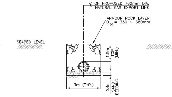
The proposed subsea gas pipeline for the BPPS (‘BPPS Pipeline’) will connect the LNG Terminal with the GRS at the BPPS and is approximately 30 inches (30”) in diameter and 45 km in length. It is a requirement that all subsea pipelines in HKSAR waters must be buried below the seabed. Burial depth when considered with rock armour provides the required level of pipeline protection. The actual burial depth below seabed is dependent on the marine and subsoil conditions along the pipeline routes. For areas that are considered to pose a threat to the integrity of the pipeline through anchor drop/drag, additional protective measures are required such as rock armour placement. The pipelines would be externally coated with an anti-corrosion coating and would also be concrete weight coated. Based on the latest engineering development, different pipeline trench designs have been developed to provide the range of pipeline protection required for the BPPS Pipeline, each of them is described below:
§ Trench Type A: This trench is to be formed by JETTING (see Figure 2.1);
§ Trench Type B: This trench is to be formed by JETTING (see Figure 2.2);
§ Trench Type C: This trench is to be formed by JETTING (see Figure 2.3);
§ Trench Type D: This trench is to be formed by JETTING (see Figure 2.4);
§ Trench Type E: This trench is to be formed by JETTING (see Figure 2.5);
§ Trench Type F: This trench is to be formed by DREDGING (see Figure 2.6);
§ Trench Type G: This trench is to be formed by DREDGING at the top 1.5m and then by JETTING of 6.5m further for the subsea cable sterile corridors (see Figure 2.7).
§ Trench Type 1: This trench is to be formed by DREDGING
(see Figure 2.8);
Figure 2.1 Trench Design (Type A)
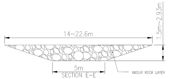
Figure 2.2 Trench Design (Type B)
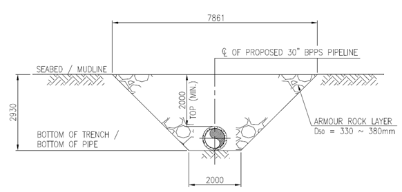
Figure 2.3 Trench Design (Type C)

Figure 2.4 Trench Design (Type D)
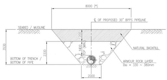
Figure 2.5 Trench Design (Type E)
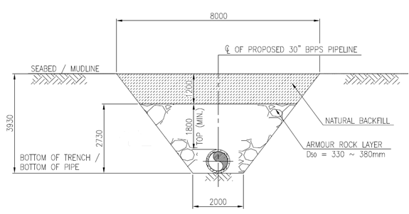
Figure 2.6 Trench Design (Type F)
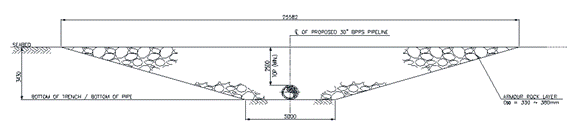
Figure 2.7 Trench Design (Type G)
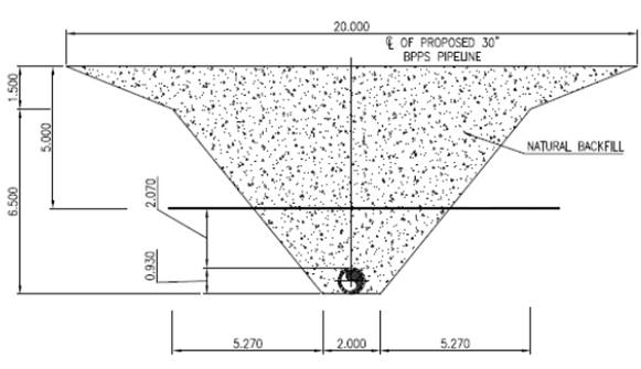
Figure 2.8 Trench Design (Type 1)
3.
Methods for Laying and Burying
the BPPS Pipeline
The sequences and procedures for laying and burying the BPPS Pipeline and the latest construction methods at different sections of the BPPS Pipeline are discussed separately in the Pipeline Construction Plan in accordance with Condition 2.8 of the FEP. In general, the following procedures will be conducted for laying and burying the BPPS Pipeline:
§ Pre-survey and removal of obstructions;
§ Pre-trenching works to form the required trench design profile;
§ Pipelaying using a conventional pipeline laybarge;
§ Post-trenching works to form the required trench design profile to install the pipeline to the required depth;
§ Rock armour placement by a conventional derrick barge or side dump vessel to cover the installed pipeline with the required rock armour; and
§ Hydrotesting to ensure the integrity of the installed pipeline.
A summary of the BPPS Pipeline construction methods together with the dredging and jetting lengths are shown in Table 3.1 below and Figure 3.1.
Table 3.1 Overview of Pipeline Construction Methods and Trench Designs
|
Description |
Section Length [km] |
KP (km) |
Proposed Trench Type |
Construction Method |
|
|
From |
To |
||||
|
Pipeline Riser |
0.1 |
0.0 |
0.1 |
Type A |
Dredging |
|
Jetty Approach to South of Soko Islands |
8.8 |
0.1 |
1.49 |
Type B |
Jetting |
|
1.49 |
2.75 |
Type G |
Dredging, followed by Jetting |
||
|
2.75 |
3.55 |
Type E |
Jetting |
||
|
3.55 |
4.43 |
Type G |
Dredging, followed by Jetting |
||
|
4.43 |
8.9 |
Type C |
Jetting |
||
|
Southwest of Soko Islands |
3.2 |
8.9 |
12.1 |
Type C |
Jetting |
|
Adamasta Channel |
3.5 |
12.1 |
15.6 |
Type C |
Jetting |
|
Southwest Lantau |
5.7 |
15.6 |
21.3 |
Type C |
Jetting |
|
West of Tai O |
4.9 |
21.3 |
26.2 |
Type C / D |
Jetting |
|
West of HKIA |
5.3 |
26.2 |
31.5 |
Type E |
Jetting |
|
Sha Chau to Lung Kwu Chau |
6.0 |
31.5 |
37.5 |
Type C |
Jetting |
|
Lung Kwu Chau to Urmston Anchorage |
3.6 |
37.5 |
41.1 |
Type C |
Jetting |
|
Urmston Road |
1.8 |
41.1 |
42.9 |
Type F |
Dredging |
|
West of BPPS |
2.0 |
42.9 |
44.9 |
Type E |
Jetting |
|
Pipeline shore approach at BPPS |
0.1 |
44.9 |
45.0 |
Type 1 |
Dredging |
|
Note: (1) No more than two jetting machines will be used for the construction of the subsea gas pipeline of the Project. In addition to existing relevant mitigation measures, the minimum separation distance between the two jetting machines for avoiding cumulative impact is 5km for most of the pipeline sections, except when one jetting machine is working at the subsea cable sterile corridors (i.e. KP1.49 – KP2.75 and KP3.55 – KP4.43). When one jetting machine is working at the subsea cable sterile corridors, no other jetting machine will work concurrently within KP0.0-KP14.25, i.e., between the Jetty and Adamasta Channel.
|
|||||
4.
Dredging and Jetting
Operations for the BPPS Pipeline
4.1
Dredging
and Jetting Rates, Types and Numbers of Dredging and Jetting Plants
Appropriate dredging and jetting rates, types and numbers of dredging and jetting plants for the BPPS Pipeline will be adopted to minimise potential water quality impacts from elevated suspended solids following the mitigation measures as stated in Table A.2 of the Updated EM&A Manual of the Project and are summarised in Table 4.1 below. The types of dredging and jetting plants are indicated in the sub-sections below.
4.1.1
Dredging
Plants
The following three types of dredging plants will be adopted for the construction of the BPPS Pipeline:
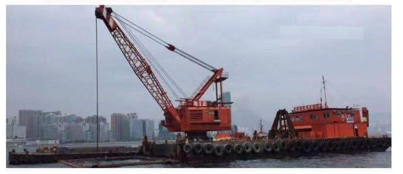
§ Grab dredger for dredging operations (see indicative grab dredger in Figure 4.1);
§ Split hopper barge to be berthed adjacent to the grab dredger to contain the dredged materials from the grab dredger (see indicative spilt hopper barge in Figure 4.2); and
§ Motor tug for moving the grab dredger and split hopper barge (see indicative motor tug in Figure 4.3).
Figure 4.1 Indicative Grab Dredger

Figure 4.2 Indicative Split Hopper Barge
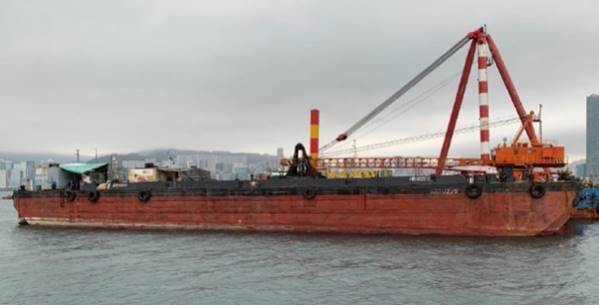
Figure 4.3 Indicative Motor Tug
4.1.2
Jetting
Plants
The following two jetting plants will be adopted for the construction of the BPPS Pipeline:
§ Jetting machine for jetting operations (see indicative jetting machines in Figures 4.4a-c); and
§ Support vessel for the positioning of trencher (see indicative support vessel in Figures 4.5a-b).
Figure 4.4a Indicative Jetting Machine
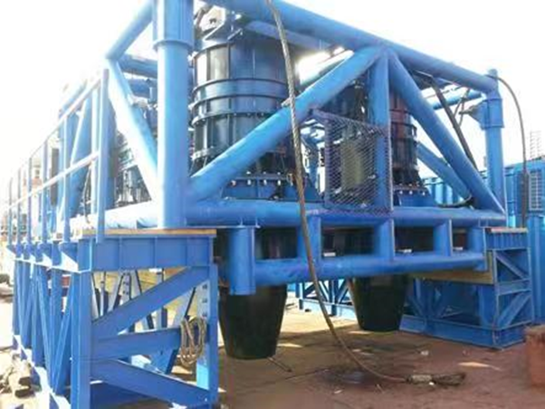
Figure 4.4b Indicative Jetting Machine
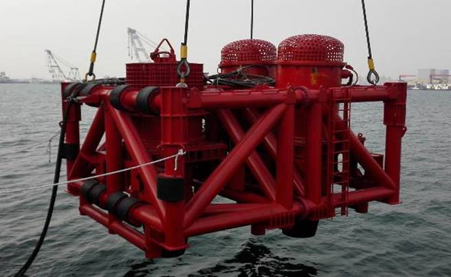
Figure 4.4c Indicative Jetting Machine
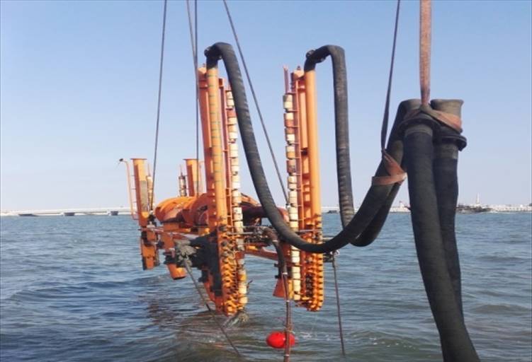
Figure 4.5a Indicative Support Vessel
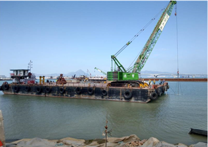
Figure 4.5b Indicative Support Vessel
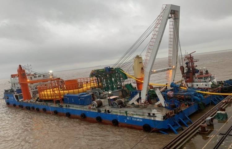
Table 4.1 Summary of Dredging and Jetting Operation and Mitigation Measures for Pipeline Construction Works
|
Work Location |
Types and No. of Plant Involved |
Allowed Maximum Work Rate |
Silt Curtain at Plants |
Silt Curtain at WSRs |
Other Measures |
|
Pipeline Riser (KP0.0 – 0.1) |
1 Grab Dredger |
8,000m3 day-1 for 24 hours each day |
Yes |
Not required |
Daily maximum of 12 hours with daylight (0700 – 1900) |
|
Jetty Approach (KP0.1 – 5.0), excluding Subsea Cable Sterile Corridors |
1 Jetting Machine (Note 1) |
1,000m day-1 for 24 hours each day |
Yes |
Not required for grab dredging; Two layers at Southern Boundary of the proposed South Lantau Marine Park (KP0.1 – 8.9) for jetting |
Daily maximum of 12 hours with daylight (0700 – 1900) |
|
Subsea Cable Sterile Corridors (KP1.49 – 2.75 & KP3.55 – 4.43) |
2 Grab Dredgers, followed by 1 Jetting Machine (Note 1)
|
8,000m3 day-1 for 24 hours each day for each dredger 720m day-1 for 24 hours each day for jetting machine |
Yes |
||
|
South of Soko Islands (KP5.0 – 8.9) |
1 Jetting Machine (Note 1) |
1,000m day-1 for 24 hours each day |
Yes |
||
|
Southwest of Soko Islands (KP8.9 – 12.1) |
1 Jetting Machine (Note 1) |
1,000m day-1 for 24 hours each day |
Yes |
Not required |
|
|
Adamasta Channel (KP12.1 – 15.6) |
1 Jetting Machine (Note 1) |
1,000m day-1 for 24 hours each day |
Yes |
Not required |
|
|
Southwest Lantau (KP15.6 – 21.3) |
1 Jetting Machine (Note 1)
|
1,500m day-1 for 24 hours each day |
Yes |
Not required |
Avoid the peak months of Chinese White Dolphin (CWD) calving (May and June) |
|
West of Tai O to West of HKIA (KP21.3 – 31.5) |
1 Jetting Machine (Note 1) |
1,500m day-1 for 24 hours each day from KP26.2 to 21.3 720m day-1 for 24 hours each day from KP31.5 to 26.2 |
Yes |
Not required |
|
|
Sha Chau to Lung Kwu Chau (KP31.5 – 36.0) |
1 Jetting Machine (Note 1) |
720m day-1 for 24 hours each day |
Yes |
Two layers at Western Boundary of the Sha Chau and Lung Kwu Chau Marine Park (KP31.5 – 36.0) |
|
|
Sha Chau to Lung Kwu Chau (KP36.0 – 37.5) |
1 Jetting Machine (Note 1)
|
720m day-1 for 24 hours each day |
Yes |
Two layers at Western Boundary of Sha Chau and Lung Kwu Chau Marine Park (KP36.0 – 37.5) |
|
|
Lung Kwu Chau to Urmston Anchorage (KP37.5 – 41.1) |
1 Jetting Machine (Note 1) |
1,000m day-1 for 24 hours each day |
Yes |
Two layers at NW corner of Sha Chau and Lung Kwu Chau Marine Park (KP37.5 – 41.1) |
|
|
Urmston Road (KP41.1 – 42.9) |
1 Grab Dredger
|
8,000m3 day-1 for 24 hours each day
|
Yes
|
Not required
|
|
|
West of BPPS (KP42.9 – 44.9) |
1 Jetting Machine (Note 1) |
1,000m day-1 for 24 hours each day |
Yes |
Two layers at CR1, CR2 |
|
|
Pipeline shore approach at BPPS (KP44.9 – 45.0) |
1 Grab Dredger |
1,500m3 day-1 for 24 hours each day |
Yes |
Two layers at CR1, CR2 |
|
|
Notes: (1) No more than two jetting machines will be used for the construction of the subsea gas pipeline of the Project. In addition to existing relevant mitigation measures, the minimum separation distance between the two jetting machines for avoiding cumulative impact is 5km for most of the pipeline sections, except when one jetting machine is working at the subsea cable sterile corridors (i.e. KP1.49 – KP2.75 and KP3.55 – KP4.43). When one jetting machine is working at the subsea cable sterile corridors, no other jetting machine will work concurrently within KP0.0-KP14.25, i.e., between the Jetty and Adamasta Channel. (2) CR1 and CR2 denote the coral colonies identified at the artificial seawall at BPPS. |
|||||
([1]) Application for variation of an environmental permit for FEP-01/558/2018 was undertaken and the latest FEP (FEP-01/558/2018/A) was issued on 6 November 2020.
([2]) Application for variation of an environmental permit for FEP-03/558/2018/A was undertaken and the latest FEP (FEP-03/558/2018/B) was issued on 25 August 2021.
([3]) Application for variation of an environmental permit for FEP-02/558/2018 was undertaken and the latest FEP (FEP-02/558/2018/A) was issued on 22 December 2020.
([4]) The environmental acceptability for the proposed variation of the numbers of jetting plants has been confirmed in an environmental review conducted for the proposal of two jetting machines submitted under the Application for Variation of an Environmental Permit (Application No. VEP-597/2020). The application package can be accessed via: https://www.epd.gov.hk/eia/register/permit/latest/VEP5972021_appdoc.pdf